Lab integration
(Managed by Prof. Glenn McDowell)
Introduction
WA5 is concerned with the holistic interpretation of complementary experimental and numerical results generated by other parts of the programme.
As WA2 has explored an increasing range of interventions and combinations of interventions, WA5 has evolved into a more detailed integration of lab results and of numerical modelling from Southampton and Nottingham. This has two benefits. First, where results differ, we have been able to identify and quantify the impact of initial assumptions and a number of secondary influences such as boundary conditions. This gives great confidence in the method and the applicability of results to the field situation. Secondly, when these are understood and accounted for, we are able to run test and models simultaneously in both groups to verify results through control tests and extend the number of parameters tested.
At the outset of Track 21, Work Area 5 was to focus on system integration: integrating the outputs of all WAs but particularly WAs 1 and 2, to investigate the effects on track system performance of combinations of sub-base type, train loading, new ballast specifications, sleepers and other track component modifications. Complementary loading combinations were to be tested in full-scale laboratory rigs in both Nottingham and Southampton. The objective was to investigate, holistically, the effects of the interventions and innovations considered in WA2 on track system performance, ballast settlement and breakage, and the influence of sub-base conditions (WA1).
Returning to the original vision for WA5, some of the more promising combinations of interventions are indeed now being tested, following on seamlessly from WA2.
Initial objectives
Methods
Full scale laboratory experiments to investigate combinations of different sub-base type; ballast depth, condition and specification; sleeper geometry and material; and other interventions such as soft reinforcement, ballast mats and under-sleeper pads, will be carried out using the Nottingham Railway Test Facility (RTF) and the Southampton Sleeper Test Facility (STF). The RTF consists of three sleepers embedded in ballast, housed in a large concrete pit, with three actuators applying cyclic vertical loads in sequence to simulate a passing train.
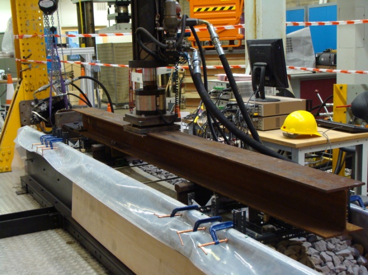
The RTF also incorporates a fully operational tamping bank which can be used to simulate maintenance operations. It is described in detail by Brown et al (2007). The STF consists of a full length sleeper embedded in ballast, to which both vertical and horizontal loads can be applied, simulating the forces generated by trains traversing curves. The horizontal forces generated during the passage of a train through a switch can also be replicated.
In both the RTF and the STF, it is possible to apply in the order of a million cycles to a particular combination of sleeper, ballast and sub-base during a typical test, thereby simulating in-service loading conditions. Instrumentation and methods used to measure the performance of the track system include pressure cells (Technimeasure) to estimate vertical stresses just below the ballast/sub-base interface, installed under and between the sleeper locations to understand the influence of the sleeper contact area and ballast interlock on the transfer of the load into the sub-base displacement transducers (LVDTs) to measure total sleeper settlement and dynamic deflection, sub-base settlements (using LVDTs with spindles passing through the ballast to bear on plates resting on the sub-base), and vertical movements of selected ballast particles (by attaching LVDT spindles directly to them) a coating such as lamp black on the underside of a sleeper to highlight the contact points with the ballast, the development of which can be deduced from photographs taken sequentially as the number of load cycles is increased periodic inspection of individual ballast particles for particle breakage accelerometers, rigidly attached to a moving object, to measure acceleration and deduce velocity and dynamic displacement by integration and appropriate signal processing geophones to measure velocity directly, and deduce dynamic displacement by integration (with appropriate signal processing).
The key to obtaining useful measurements within the ballast is to build up information on the way in which the magnitude of ballast movements is distributed relative to the location of the dynamic load through the sleeper. Consideration will be given to developing new and improved methods of measurement and visualisation, for example intelligent (instrumented) ballast particles for easier tracking of velocity and displacements and optical techniques. Synergies between instrumentation developed for the RTF, the STF and those used in field studies are anticipated – for example, geophones as used in the field by Bowness et al (2007) have not yet been used in the RTF or the STF.
Key outputs, impacts and inputs to other Work Areas
- an improved understanding of the relative influences of sleeper material and geometry, ballast type and grading and sub-base behaviour on resilient modulus, durability and long-term performance of ballasted track systems (input to WAs 3 and 6)
- optimised combinations of aggregate gradings, sleeper types and ballast treatments to reduce permanent deformation and maintenance frequency and therefore maintenance costs (input to WA 6)
- potentially, an understanding of the benefits of more highly engineered forms of track.